
محاسبات سازه و درایو درِ کامیون رو شرکت پارس بهشرق
Given Data:
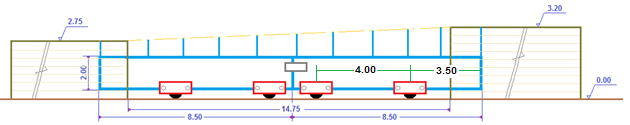
Doors Dimensions :
L = 8.5 (m)
h = 2.7 ~3.15 (m)
Estimated Weight of each semi door, Wd = 13,000 (N)
Estimated Weight of each rail system, Wrail = 25,000 (N)
Wind Force:
Drag Coefficient for a rectangular plate, Cd = 1.4
A = 8.5 x 2.5 = 21.25 (m²)
Wind Speed, V = 25 m/s
Wind Force, Fwind = 0.63Cd x V² x A (N) = 0.63 x1.4 x 25² x 21.25 = 11,715 (N)
Distributed wind load = 11715/21.25 = 551 N/m²
Stability Rollers :
Wind pressure might roll over the door if we don’t take any consideration on it
Stability governs whenever resistant torque,
Wind arm,
Roller Distance,
We have selected as a first try , ;
Dmin = 6 mm we take D=20 mm
Now we should check the roller shaft deflection
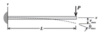
Roller Shaft Deflection
Deflection is often the more demanding constraint. Many shafts are well within specification for stress but would exhibit too much deflection to be appropriate. Deflections at gears, pulleys, and rollers should not exceed about 0.125 mm. For such mechanisms deflection must be 1.5% length, around 1 mm.
it is so big! So we will reselect D=36 mm
it would be good
Door Deflection
Deflection of the door is a crucial and demanding constraint. Its deflection as a complex beam with 4 constrain can be find based on the following fomula:
Where:
= 7.5 (m) and
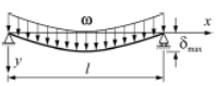
E = 200 Gpas
I = 679 + 2 x (1.8675 + 6225) = 13,132 ()
So, it would be OK
Traction Force:
Coefficient of rolling friction for steel wheels on steel rails), = 0.5 (mm)
Wdoor = [2(8.5+2) 18.8+ 2(2 X 8.5) x 16 ] = 1.1 x [395+544]= 1032 (kg) We assume 12,000 (N)
Wi = Wd x (5²-3.5²)/(2 x 4 x 8.5) = 2,250 (N) Load on idler wheel
Wdrive = Wdoor x (7.5²-1²)/(2 x 4 x 8.5) = 9,750 (N) Load on drive wheel
Effective wheel radius, Rw = 50 (mm)
Ft = 9750 x 0.5 /50 = 98 N/m
Drive system selection:
- Drive Wheel
- Rack and Pinion
- Drive Wheel, Permitted Starting Acceleration:
The wheel slips as soon as the peripheral force Fu on the wheel becomes greater than the friction force Fr:
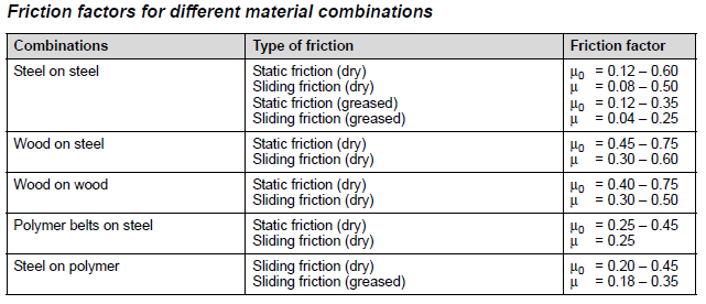
The equation we started with, is an approximation, and friction is actually a far more complicated phenomenon that that simple law suggests. For example car tyres deform and can key into irregularities on the road to increase the friction. Conversely in our situation, rails in winter have a slippery surface and wheel slippage is likely.
To avoid the slippage even in winter we can use a = 0.4(m/s²)
Speed, V= 6 m/min V=0.1 m/s
V < a . t t > 0.25 ( sec. )
It is worthy to mention that the drive should be equipped with a soft starter to set accelerating time.
V = Rω
Power:
Based on the below tables Load Factor,KA and Operating Time Factor, bB are respectably 1.25 and 1.2. If we assume safety factor 1.4 (it is around 1.1 to 1.4), output torque of gearbox can be find:
We take P= 0.33 kW
Where:
with speed ratio, i = 76 ~ 80
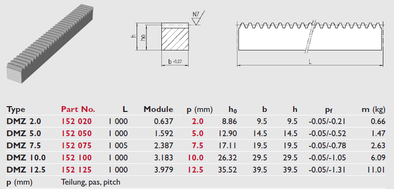
- Rack and Pinion
Pinion can be selected based on the following table. We can select as a first try P= 12.5 mm, Z = 20,
d =32 mm, u = 10 mm, Do = 79.77 mm, Dk = 87.54 mm, t = 35.3 mm, Z = 20, L1 = 20 mm, L2 = 40 mm
Material: 16MnCr5 DIN 1.7131;
Teeth: pressure angle α=20° straight teeth hardened, ground, crowned
V = Rω
 |
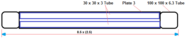
Specifications:
All semi doors ( 4 units) equipped with:
- 2 x Maintenance-free wheels
- 6 x Bottom guiding wheels
- 8 x Wall mounted guiding wheels
- 72 m x IPB 200 and U x200 as the supporting system
- 72 m x 30×30 rail
- 2 x0.250 kW geared motor
- 8 x 2.25m x 8.5m door cover plate
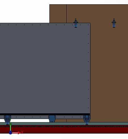
Detail Drawings
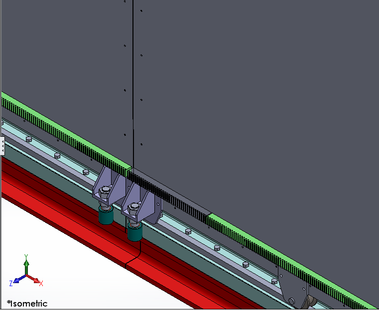 |
|
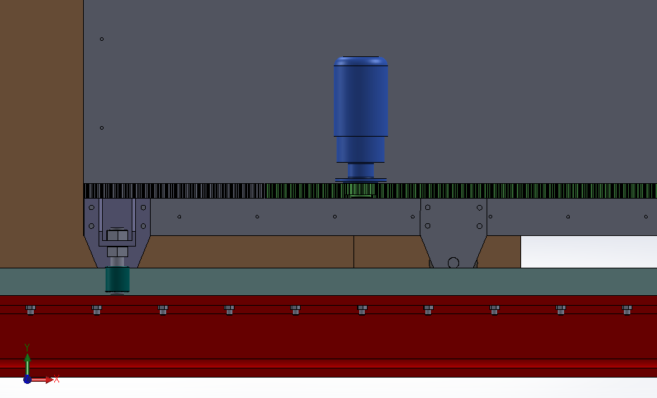
| Stabilizer Rollers and Rack System | |
 |
|
| Rail and Wall Guide | |
 |
|
| Drive System and Stablizer | |
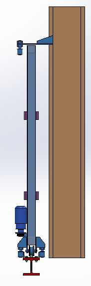 |
| Sliding Door with Supporting Wheels and Guide Rollers |